OOF2: The Manual
| 4.7.6. Move Nodes | ||
|---|---|---|

|
4.7. Toolboxes |  |
The Move Nodes Toolbox allows the position of Skeleton Nodes to be
set manually. Unless Nodes moved in this way are subsequently
pinned, other Skeleton
modification routines may move them away from their assigned
spots.
Figure 4.12 shows the arrangement of
the Toolbox. The Toolbox operates in one of two modes, set by the
buttons at the top marked Mouse and
Keyboard. In both modes, the boxes labelled
x and y show the current
position (in physical
coordinates) of the Node being moved, and the boxes
labelled shape energy and
homogeneity show the
change in the shape
energy and homogeneity
of the Elements surrounding the moving Node.
Figure 4.12. The Move Nodes Toolbox
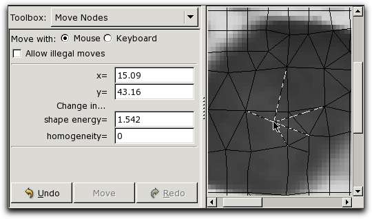
The Move Nodes Toolbox and a portion of the Canvas, showing
a Node in motion.
To move a Node in Mouse mode, simply click on or near the Node
in the Canvas, and drag it to its new position. (The Node's
Skeleton must be in the topmost Skeleton Layer in the Canvas.) While
the Node is being dragged, ghostly versions of the Segments
connected to the Node are drawn, and the displayed position,
shape energy, and homogeneity are continuously updated.
Moving a Node in Keyboard mode allows for more precise
placement, if you happen to know the desired position numerically.
Switch to Keyboard mode and click
on the Node to be moved. Its position will be entered in the
x and y boxes, and the
Node will be highlighted in the Canvas by a pink dot.[11]
To move the Node, type new coordinates in the boxes and click
the Move button at the bottom of the toolbox.
In either mode, moving a Node triggers the OOF.Graphics_n.Toolbox.Move_Nodes.MoveNode
command.
Moves that create illegal
Elements will be rejected unless the box marked Allow
illegal moves is checked. It can be convenient
to temporarily create illegally shaped Elements when moving
multiple Nodes, as long as no illegal Elements remain at the end.
During a move, the Toolbox indicates if the moving Node is in an
illegal position. At other times, it indicates the number of
illegal Elements in the Skeleton.
The and buttons at the bottom of the Toolbox are duplicates of the and buttons on the Skeleton Task Page.
[11]
To change the appearance of the pink dot, use the
Layer Editor to modify the MoveNodeDisplay that's assigned to
the topmost Skeleton. This is a predefined Layer. It will be
necessary to enable List
All Layers in the Settings menu first.
|
|
 |
|
| 4.7. Toolboxes |  |
4.8. The Layer Editor |