OOF2: The Manual
Anneal (Anneal) |
||
|---|---|---|

|
6.5.2. Subclasses |  |
Name
Anneal (Anneal) — Move nodes randomly to improve element shape and homogeneity.
Synopsis
Anneal(targets, criterion, T, delta, iteration)
Details
-
Base class:
SkeletonModifier -
Parameters:
targets- Which nodes to move. Type: An object of the
FiddleNodesTargetsclass. criterion- Acceptance criterion Type: An object of the
SkelModCriterionclass. T- Failed moves will be accepted if T>0 and exp(-diffE/T) > r, where diffE is the energy gained and r is a random number between 0 and 1. Type: A real number.
delta- Width of the distribution of attempted node motions, in units of the pixel size. Type: A real number.
iteration- Iteration method. Type: An object of the
IterationManagerclass.
Description
Anneal is a Skeleton modifier that
moves Nodes to random positions, accepting or rejecting moves
according to the given criterion. It is similar
to a simulated annealing simulation in statistical mechanics, from
which it gets its name. Instead of minimizing the free energy of a
system of particles, it minimizes the effective energy
of a Skeleton.
The general procedure for a single iteration of
Anneal is as follows:
-
Collect target nodes according to the given
targetsparameter. The collectedNodesare re-ordered randomly to remove any potential artifacts from the original ordering ofNodes. This re-ordering is repeated at every iteration. -
Give each
Nodea single chance to move to a randomly assigned new position. OOF2 computes the new position fromand are random numbers chosen from a Gaussian distribution of width
deltaand mean 0.0.deltais in units of theMicrostructurepixel size.Figure 6.66(a) shows a node (the big red dot) that is about to move to a new position. Before making the move, OOF2 computes the total effective energy of all of the neighboring elements of the node.
-
After moving each
Node, the given acceptancecriteriondecides whether or not the move is acceptable. -
If the move is unacceptable according to the acceptance
criterion, OOF2 may still accept the move if the annealing is being done at a non-zero temperature. The parameterTsets the effective temperature of the annealing process. Unacceptable moves are accepted with a probabilitywhere is the difference between the effective energies of the new and old
Elementconfigurations.
Figure 6.66. Annealing
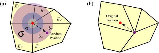
(a) A node moves by
and
. The
node move affects five neighboring elements,
E0, E1,
E2, E3, and
E4. (b) The node has moved to a
new position. If the move doesn't satisfy the given
acceptance criterion (computed based on
its five affected elements), it'll be rejected and the
node will move back to its original position.
Successful annealing usually requires a number of iterations. On
each iteration, OOF2 makes one attempt to move each node. The
number of iterations is controlled by the
iteration parameter, which can be set to perform
a fixed number of iterations or to stop after some condition is
satisfied. See IterationManager
for the details.
Statistics for each step of the annealing process are printed in the OOF2 Message window. For example,
    Iteration 1: E = 1.1916e+01, deltaE=-1.2495e-01 ( 1.049%), Acceptance Rate = 19.1%
    Iteration 2: E = 1.1391e+01, deltaE=-1.7564e-01 ( 1.542%), Acceptance Rate = 25.5%
    Iteration 3: E = 1.0638e+01, deltaE=-1.1883e-01 ( 1.117%), Acceptance Rate = 22.3%
    Iteration 4: E = 1.0095e+01, deltaE=-1.4345e-01 ( 1.421%), Acceptance Rate = 21.0%
    Iteration 5: E = 9.5440e+00, deltaE=-8.3725e-02 ( 0.877%), Acceptance Rate = 21.0%
The listing shows the iteration number, the total energy
(E) of the Skeleton, the absolute
change in energy (deltaE) during
the iteration, the percentage change in energy, and the move acceptance rate. If
the change in energy or the acceptance rate gets too small, the
annealing process is not being effective at improving the Skeleton.
Using ConditionalIteration as the
iteration parameter can stop the process when it
becomes ineffective.
Figure 6.67 shows a Microstructure containing
three pixel types. The initial Skeleton has been refined once, but doesn't do
a good job of representing the geometry of the Microstructure. Refining
further might help, but it would create a lot of small Elements,
which might not be desirable. Anneal can
improve the Skeleton without creating new Elements.
Figure 6.67. An Un-annealed Skeleton
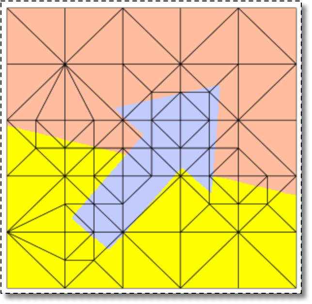
A Microstructure (displayed by material
color) and a slightly refined Skeleton.
Figure 6.68 displays the results of annealing
the Skeleton. In these images, the Elements are drawn with the color
of their dominant pixel. This is a good way to estimate Skeleton
quality — in a good Skeleton the Element colors match the pixel
colors. The un-annealed Skeleton in the top left is clearly not a
good representation of the Microstructure.
All of the annealing steps in Figure 6.68 were
done with T=0, iterations=20, and
alpha=0.8. The first two steps were done with
delta=5. (The image is approximately 300 pixels on a
side, so individual pixel motions are about 1/60th of the size of
the image.) After one annealing step, the border between the orange
and yellow regions is more or less straight and the blue arrow is
beginning to be resolved. After two steps, the representation is
pretty good. (Whether it's good enough depends on what your needs
are.) However, there are some very narrow poorly shaped Elements.
This is because the annealing was done with alpha=0.8,
which favors homogeneity over
shape. Applying Rationalize with alpha=0.5
eliminates some of these narrow Elements, leading to the Skeleton in
the bottom right in the figure. Notice that the sides of the blue arrow
are not quite straight. Another annealing step, this time with
delta=1 moves the Nodes by small amounts, and nearly
perfectly matches the Element edges to the Microstructure boundaries. A
final rationalization then removes the last poorly shaped Element.
Figure 6.68. Annealing the Skeleton
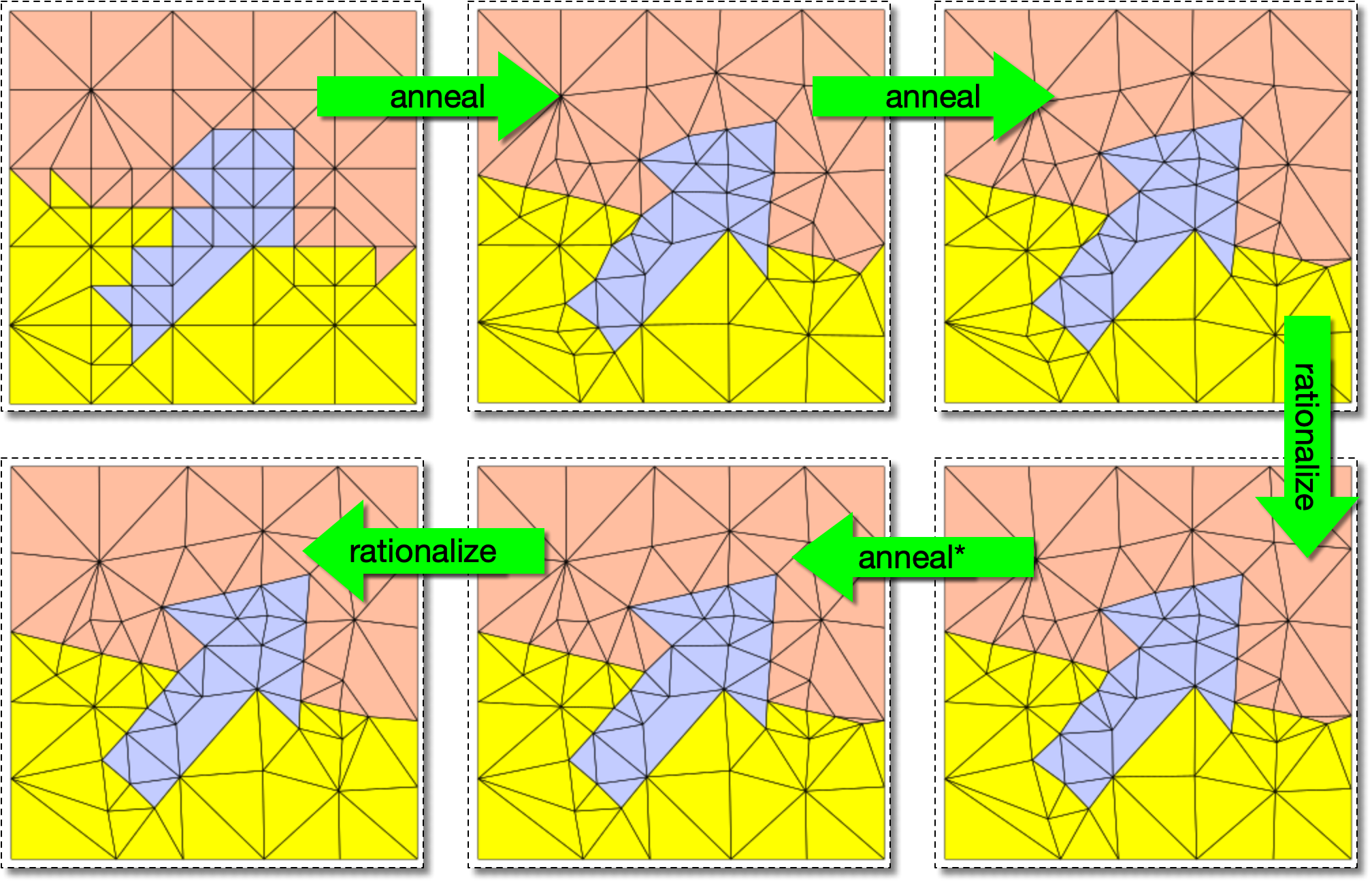
Skeleton from Figure 6.67. The
Elements are displayed with their material
color. The top left image contain the same un-annealed
Skeleton as in Figure 6.67. The first
two annealing steps have delta=5 and third (marked
with an asterisk) has delta=1.
Figure 6.69. Comparison between the Annealed Skeleton and the Microstructure
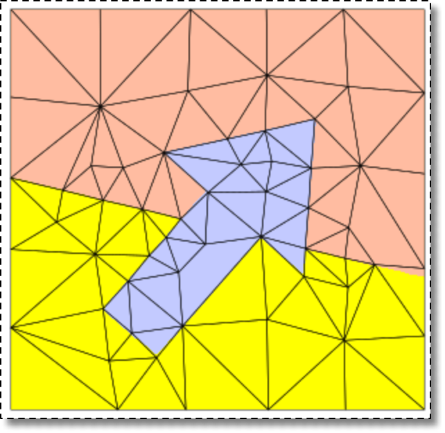
The final Skeleton from Figure 6.68,
displayed on top of the Microstructure material image from Figure 6.67. The only spot where the
Skeleton visibly deviates from the material boundaries is at the
right end of the yellow/orange interface. That could be
cleaned up easily with SnapNodes.
Disclaimer.
Because the Nodes are addressed in a random order and are
displaced by random amounts, annealing is not a deterministic
process. Your mileage will vary. The results above may not be
reproducible. You may need to adjust the parameters, run more
annealing steps, or use other SkeletonModifiers along with
Anneal.
![[Tip]](IMAGES/tip.png) |
Tip |
|---|---|
|
Even though the example shown above concentrates on resolving
material boundaries (meaning it puts more emphasis on homogeneity
than shape), |
|
Tip |
|---|---|
|
A good way to anneal efficiently is to apply it only to |
|
|
 |
|
Angles (AngleDirection)
|
 |
Automatic (AutomaticRationalization) |