OOF2: The Manual
Snap Nodes (SnapNodes) |
||
|---|---|---|

|
6.5.2. Subclasses |  |
Name
Snap Nodes (SnapNodes) — Move nodes directly to pixel boundaries.
Synopsis
SnapNodes(targets, criterion)
Details
-
Base class:
SkeletonModifier -
Parameters:
targets- Which segments to snap. Type: An object of the
SnapNodeTargetsclass. criterion- Acceptance criterion Type: An object of the
SkelModCriterionclass.
Description
SnapNodes moves Nodes to improve the
Elements' Homegeneity Energy.
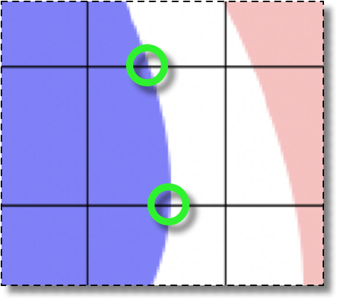
If an Element edge crosses over regions of the Microstructure belonging to
different pixel categories, then
SnapNodes tries to move one of the Element
corners to the crossing point. These points are called
“transition points”, and are illustrated in Figure 6.107. See Section 2.4.4 for more on transition
points and how they're detected.
The general procedure for snapping Nodes is as follows.
-
Scan the current
Skeletonand build a list of candidateNodesfor snapping. The candidates are identified by thetargetsparameter. Randomize the list. -
-
Loop over the candidate's neighbor nodes, M.
-
If the segment NM hasn't been examined already, try moving each node, or both at once, to all the transition points on any of their
Segments. Pick the combination move that best satisfies the specified acceptancecriterion. -
Remove node N from the list of candidate nodes. Move node M to the top of the list, so that it's examined next.
-
Go back to step 2 until the list is empty.
-
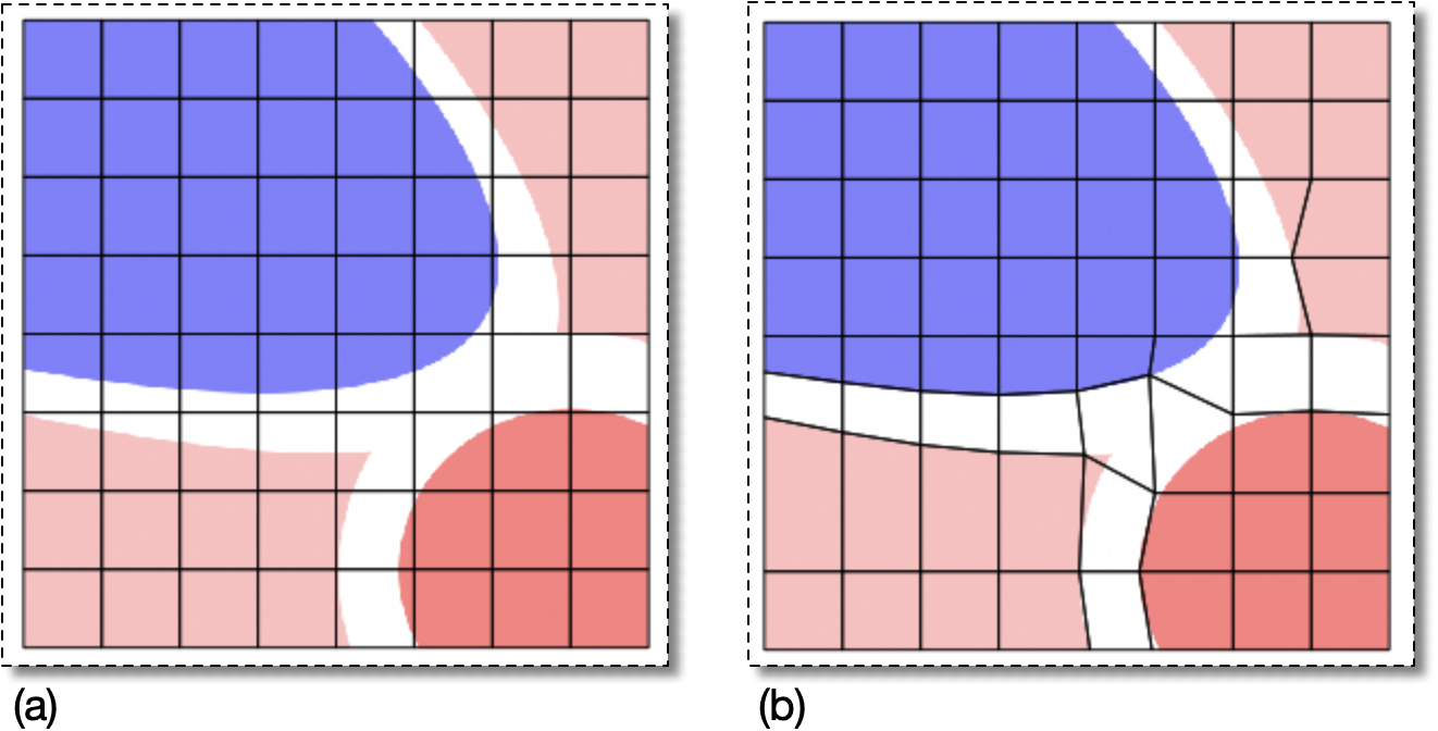
Figure 6.108 shows a Skeleton that features some
heterogeneous elements and the result of applying
SnapNodes with targets=SnapAll() and
criterion=AverageEnergy(alpha=0.7)
to it. Some, but not all, of the material boundaries have been
resolved nicely.
Snapping Nodes (like all Skeleton modifications) tends to produce
badly-shaped elements when done with large values of
alpha. The Skeleton in Figure 6.109(a) is the result of increasing
alpha to 0.9 in the previous operation. The
element edges follow the upper-right part of the blue region and the
upper-left part of the red region much more closely. However the
three Elements marked in green and labeled “Degenerate”
are very badly shaped. They appear to be triangles, but the two
smaller ones are quadrilaterals with a very short side where they
join, and the other is actually a quadrilateral with a nearly
180° angle at one node. The shape energy
of the first two is almost maximally bad, 0.99, and the third's is
0.93.
The upper two green Elements labeled “Inhomogeneous” in
Figure 6.109 illustrate a configuration that
is impossible to improve with SnapNodes
alone. It's not possible to fix these Elements just by moving
Nodes.
However, it can be useful to allow SnapNodes
to create badly shaped Elements, and to clean up afterwards by
applying other tools. The Skeleton in Figure 6.109(b) is the result of applying Rationalize and SplitQuads to the problem Elements in
(a). These tools can often fix messes left behind by
SnapNodes.
Figure 6.109. Snapping Nodes with a Large alpha
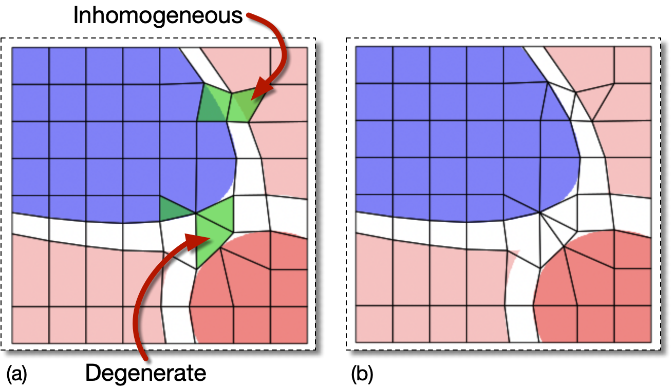
(a) The result of using SnapNodes with
a large alpha, 0.9,
on the Skeleton in Figure 6.108(a). It has
produced some badly shaped Elements and failed to make all of
the rest homogeneous.
(b) The result of applying Rationalize and SplitQuads to the Skeleton in (a).
The degenerate quadrilaterals have been converted to triangles
by merging nodes (although that's not obvious in the image)
and by splitting the large obtuse angle. The inhomogeneous
quads have each been split into two homogeneous triangles.
|
|
 |
|
Heterogeneous Segments (SnapHeterogeneousSegments)
|
 |
Selected Elements (SnapSelectedElements) |