OOF2: The Manual
| 3.6. Materials | ||
|---|---|---|

|
Chapter 3. Task Pages |  |
The Materials Page is where Materials are built and assigned
to pixels in a Microstructure. It is the only OOF2 page (other than
the Introduction Page) that does not begin with a Chooser for
selecting a Microstructure, Skeleton, or Mesh. This is because
Materials exist independenly of Microstructures, allowing them to be
easily shared among different Microstructures.
The Materials Page consists of two panes, as shown in Figure 3.8. The Property Pane is for
setting the parameters for Properties. The Material Pane
creates and manipulates Materials and assigns them to pixels
in a Microstructure.
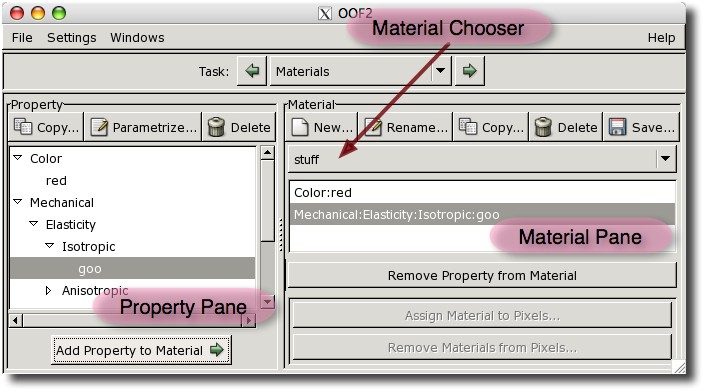
Most of the Property Pane is occupied by a hierarchical list
of Properties. This includes the predefined
unnamed Properties, and the
user-defined named Properties. In
Figure 3.8 the highlighted
Property named “goo” is a named isotropic
elasticity Property. It appears in the hierarchy below its
unnamed parent, Isotropic, which appears below
its parent, Elasticity, which is below
the top level category, Mechanical. Clicking on a Property
in the list selects it for further operations.
Double-clicking a Property is the same as single-clicking it
and pressing the
button. Names in the list that correspond to hierarchy levels
but not to Properties (such as “Elasticity” or
“Anisotropic”) cannot be selected.
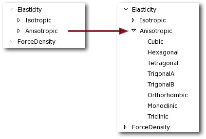
Clicking on the triangles to the left of the property names collapses and expands levels of the hierarchy. Figure 3.9 shows two views of the same section of the list. The anisotropic elastic property hierarchy is collapsed on the left and expanded on the right.
The three buttons above the Property List make changes to the list.
-
The button creates a named copy of the
Propertycurrently selected in the list. The currently selectedPropertycan be either named or unnamed. The button brings up a dialog box for naming the copiedProperty. -
The button brings up a dialog box for setting the parameters of the currently selected
Property. Property parametrization dialogs are discussed in below. The parameters are assigned to thePropertywhen the button is pressed in the dialog box. -
The button deletes the selected
Property. It can only be applied to namedProperties. The predefined unnamedPropertiescannot be deleted.
Below the Property list is the button, which adds the
currently selected Property to the Material that is
currently selected in the Material Pane.
One Property can be added to more than one Material.
Clicking the
button or double-clicking on a Property in the Property List
brings up a dialog box for setting the parameters of the
chosen Property. Property dialogs have a couple of notable
features.
-
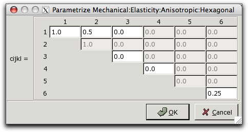
Many properties contain a number of related parameters. Only the independent ones can be set, but it can be convenient to see all of them. For example, Figure 3.10 shows the dialog box for the hexagonal elasticity property, whose parameter is a HexagonalRank4TensorCij object. The dialog box has entries for each of the components of the tensor. Some of the entries are grayed out, meaning that they cannot be set. Some of these (such as C14) are always zero for this
Property, and some (such as C22) are constrained to be equal to another entry (C11, in this case). Changing the value of C11 will also change the value of C22. Hexagonal rank 4 tensors have only 5 independent entries, but the dialog box contains 6 active entry fields. This is because there is a non-trivial relationship between values (in this case, C66=(C11-C12)/2). Changing the value of any one of the related entries will change the value of the others so that the constraint is always satisfied.
Sometimes there can be more than one way to specify a
Property. For example, isotropic elasticity can be specified in terms of the components of the elastic modulus tensor, or by giving the bulk and shear moduli, or in Lamé coefficients. The dialog boxes contain a pull-down menu for selecting the preferred representation for such parameters. Figure 3.11 illustrates this for the ColorProperty. OtherPropertiesthat have multiple representations include isotropic elasticity, cubic elasticity, and orientation.Figure 3.11. The Color Property Dialog Box
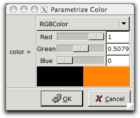
The Color Property dialog box. The menu at the top, labelled RGBColor, indicates that the Color is being specified in the RGBColor representation. (The black rectangle shows the previous value of the Color. The orange rectangle is the current value.)
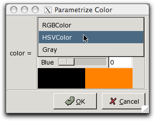
Switching to a different representation with the menu.
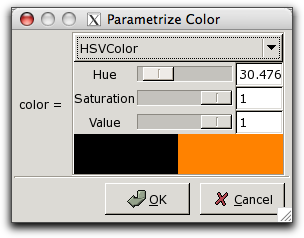
The color hasn't changed, but the sliders for setting it now use the HSVColor representation.
The Material Pane is where Properties constructed in the
Property
Pane are assembled into Materials. Materials in
OOF2 are simply lists of Properties. The Material Pane
consists of three regions (see Figure 3.8): a set of buttons at the
top, a Material Chooser and a list of Properties in the
middle, and another set of buttons at the bottom.
The Material Chooser is used to select one of the existing
Materials. The Properties contained in the selected
Material are listed below the Chooser. Clicking on a
Property in the list selects it, and also selects it in the
Property List in the Property Pane.
The buttons at the top of the Material Pane manipulate
Materials:
-
The button creates a new
Material. It brings up a dialog box asking for a name for theMaterial. After aMaterialis created, it will be automatically selected in the Material Chooser. -
The button makes a copy of the
Materialcurrently selected in the Material Chooser. -
The button deletes the
Materialcurrently selected in the Material Chooser. It does not delete thePropertiesthat were in theMaterial-- they still exist in the Property Pane and can be used in anotherMaterial. -
The button saves the currently selected
Materialand itsPropertiesin a file.
Three of the five buttons at the bottom of the Material Pane also act
on the selected Material:
The next two buttons on the left column are a pair, since they deal with
bulk Materials and Microstructures:
-
The button assigns the currently selected
Materialto pixels in aMicrostructure. It brings up the dialog box shown in Figure 3.12.Figure 3.12. Assigning Materials to Pixels
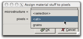
The
Materialnamed “stuff” is being assigned to all pixels in theMicrostructurenamed “microstructure”. The pull-down menu marked pixels allows theMaterialto be assigned to the selected pixels, to all the pixels, or to pixel groups (in this case, there's only one group, called “grains”).
-
The button brings up a dialog box for removing the assigned
Materialfrom specified pixels in aMicrostructure. The dialog box specifies the pixels andMicrostructurein pull-down menus like those in Figure 3.12. TheMaterialassignment is removed whether or not the pixels'Materialis the same as the Material Pane's currently selectedMaterial.
The last two buttons on the right column are used for assigning
interface Materials to interfaces and skeleton boundaries
in the Microstructures:
![[Note]](IMAGES/note.png) |
Note |
|---|---|
|
Interface materials have been disabled as of version 2.1. They will be re-enabled in a future release. |
-
The button assigns the currently selected
Materialto a list of selected interfaces and skeleton boundaries in aMicrostructure. -
The button brings up a dialog box for removing the
Materialassigned to a list of interfaces and skeleton boundaries in aMicrostructure. The dialog box groups the names of interfaces and skeleton boundaries that have the same material assignments.
|
|
 |
|
| 3.5. Active Area |  |
3.7. Skeleton |