OOF2: The Manual
| 4.7.4. The Skeleton Info Toolbox | ||
|---|---|---|

|
4.7. Toolboxes |  |
When the Skeleton Info toolbox, shown in Figure 4.10, is active, clicking the
mouse on a Skeleton on the Canvas displays information about
Elements, Nodes, and Segments in the Toolbox. Whether the Toolbox
displays Element, Node, or Segment, information is governed by the
setting of the Mode Selector buttons at the top of the Toolbox.
In all three modes, the position of the mouse click, in physical
coordinates is printed below the Mode Selector.
Figure 4.10. The Skeleton Info Toolbox
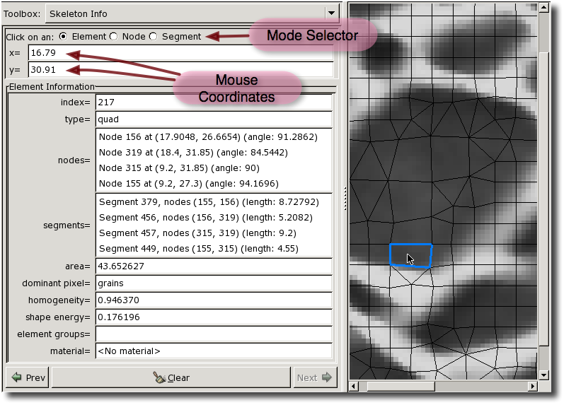
The Skeleton Info Toolbox and the Canvas, while querying an
Element. The window has been resized to show the entire
Toolbox, which would otherwise need to be scrolled to be
seen.
In all three modes, the queried Skeleton component is highlighted in
the Canvas. The button at the bottom
of the Toolbox erases the highlighting and clears the data
listing. The and
buttons on either side cycle through
the previously selected objects (changing the Toolbox mode, if
necessary).
In Element mode, the Element being queried is highlighted with a
blue perimeter,[10]
as shown in the figure, and the following data is displayed in
the Toolbox:
-
The
Element's index. This is just an integer used to identify theElement. All of theElementsin aSkeletonhave a unique index. When aSkeletonis modifed, the indices of allElementsmay be changed. -
The
Element's type, indicating its topology. -
A list of the
Element'sNodes.Nodesare listed in counterclockwise order with an arbitrary starting point. EachNode's index, position (in physical coordinates), and interior angle (in degrees) are listed.Clicking on a
Nodein the list will highlight it with an pink dot[10] on the Canvas. Double-clicking on aNodein the list will switch the Toolbox into Node Mode and display information for the chosenNode. -
A list of the
Element'sSegments, including theSegment's index, the indices of theNodesat its endpoints, and its length (in physical units).Clicking on a
Segmentin the list will highlight it with a thick pink line[10] on the Canvas. Double-clicking on aSegmentin the list will switch the Toolbox into Segment Mode and display information for the chosenSegment. -
The area of the
Element, in physical units. -
The dominant pixel of the
Element. This is a list of the pixel groups to which the pixels comprising most of theElementbelong. -
The
Element's homogeneity. -
The
Element's shape energy. -
The
Materialassigned to theElement. This is theMaterialthat will be used for anyMeshelements that are created from thisSkeleton. It is the same as theMaterialassiged to theElement's dominant pixel, unless that choice has been overridden by assigning aMaterialto anElementGroupcontaining theElement.
In Node Mode, the Node being queried is highlighted in the
Canvas with a blue dot.[10] The following information is
displayed in the Toolbox:
-
The
Node's index. Like theElementindex, this is just an integer used to identify theNode. When aSkeletonis modified,Nodesmay get new indices. -
The position of the
Node, in physical units. -
The mobility of the
Node.Nodesthat are pinned are marked as such.Nodesthat are constrained to lie on the boundaries of theMicrostructureare marked as “x only” or “y only” if they can move in the x or y directions, and as “fixed” if they cannot move at all.Nodeswith none of these constraints are marked “free”. -
A list of the
Elementswhich surround theNode, in no particular order. The index of eachElementis given.Clicking on an
Elementin the list highlights thatElement's perimeter in pink[10] in the Canvas. Double-clicking will switch the Toolbox to Element Mode and display the information for the chosenElement. -
The point boundaries of which the
Nodeis a component.
In Segment Mode, the Segment being queried is highlighted in the
Canvas with a blue line.[10] The following information is
displayed in the Toolbox:
-
The index of the
Segment. Like theNodeandElementindices, this is just an integer identifier. When aSkeletonis modified,Segmentindices may change. -
The
Nodesat the ends of theSegment. The index and position (in physical coordinates) of eachNodeis listed.Clicking on a
Nodein the list highlights it with a pink dot[10] in the Canvas. Double-clicking switches the Toolbox to Node Mode and displays the information for the chosenNode. -
The
Elementsto which theSegmentbelongs. The index of eachElementis given.Clicking on an
Elementin the list highlights thatElement's perimeter in pink[10] in the Canvas. Double-clicking will switch the Toolbox to Element Mode and display the information for the chosen -
The length of the
Segmentin physical units. -
Any edge boundaries of which the
Segmentis a component.
[10]
The color and size of the markings used to highlight the
queried Elements, Nodes, and Segments may be changed by
editing the SkeletonInfoDisplay display
Layer. This Layer is predefined and always displays the
topmost Skeleton. It will be necessary to enable List
All Layers in the Settings
menu in order to edit the Layer.
|
|
 |
|
| 4.7. Toolboxes |  |
4.8. The Layer Editor |