µMAG Standard Problem #4 results
See the problem specification.
Disclaimer
µMAG could not succeed without the contributions
of colleagues working outside NIST. Although we value the
contributions made by these colleagues, NIST does not necessarily
endorse the views expressed or the data presented in the submitted
solutions shown below.
Solution directory
-
Comparisons
- G. Albuquerque,
J. Miltat and A. Thiaville
-
R. D. McMichael, M. J. Donahue, D. G. Porter, and
J. Eicke
-
Liliana Buda, Lucian Prejbeanu, Ursula Ebels and Kamel
Ounadjela
-
E. Martinez, L. Torres and L. Lopez-Diaz
-
José L. Martins and Tania Rocha
-
P.E. Roy and P. Svedlindh
-
Massimiliano d’Aquino, Claudio Serpico,
and Giovanni Miano
-
Dmitri Berkov
-
M. J. Donahue and D. G. Porter
-
Rasmus Bjørk, E. B. Poulsen and A. R. Insinga
Submitted Solution:
M. J. Donahue and D. G. Porter
- Date:
- September 25, 2014.
- From:
- M. J. Donahue and D. G. Porter
National Institute of Standards and Technology, Gaithersburg, MD
20899
- Contact:
- Michael Donahue
An earlier contributed solution
came from the original 2D
mmSolve2D
program in
OOMMF. This new submission
comes from the
OOMMF eXtensible solver. The mesh is a 3D array of 1 nm cubes.
The exchange energy was calculated using a "six-neighbor dot
product" representation. The maximum time step was set at 0.2 ps, but
smaller time steps are taken when necessary to keep the error within
certain bounds. All other simulation components were used in their
default configuration. Data from the simulation was captured and archived
at every 1 ps of simulation time.
Results:
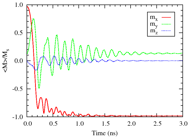
- For the first part of the problem, with the field applied
170° from the x-axis (Field 1), the maximum angle between
neighboring spins on the lattice was about 6° at about 300 ps.

a plot of the spatially averaged magnetization

and an image of the magnetization when Mx
first crosses zero. The background color indicates the z component
of magnetization, with blue directed away from the viewer and red
directed toward the viewer.
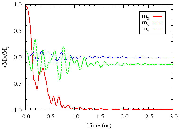
- For the second part of the problem, with the field applied
190° from the x-axis (Field 2), the maximum angle
between neighboring spins on the lattice was about 18° at about 580 ns.

A plot of the spatially averaged magnetization

and an image of the magnetization when Mx
first crosses zero. The background color indicates the z component
of magnetization, with blue directed away from the viewer and red
directed toward the viewer.
More detail on the simulations and the visualization of (a
shortened and subsampled form of) them as movies is featured
here.
Raw data:
Vector data is in the OVF 2.0 format.
Supplemental material:
Please send comments to [email protected] and join the
µMAG discussion e-mail list.
Site Directory
µMAG organization / NIST CTCMS /
[email protected]
11-NOV-2021


