OOF2: The Manual
| 4.5.2. The Pixel Info Toolbox | ||
|---|---|---|

|
4.5. Toolboxes |  |
The Pixel Info Toolbox displays information about pixels of the
topmost Microstructure and/or Image displayed in the Canvas. Data is
displayed only if the Canvas contains a Layer displaying an
Image or Microstructure. Figure 4.6 shows the
Toolbox and the Canvas.
When the mouse is clicked on the Canvas, the pixel under the mouse click is highlighted, as shown in the figure. The coordinates of the pixel are displayed in the Toolbox. A new pixel may be chosen by either clicking again on the Canvas, or by typing new coordinates into the x and y boxes in the Toolbox and clicking the button. Either action invokes the OOF.Graphics_n.Toolbox.Pixel_Info.Query command.
The Clear button resets the toolbox and un-highlights the selected pixel by invoking OOF.Graphics_n.Toolbox.Pixel_Info.Clear.
The way in which the selected pixel is highlighted in the Canvas
may be changed by editing the PixelInfoDisplay display method that
is assigned to the topmost Microstructure and Image. (Check List
All Layers in the Graphics Window's
Settings menu, then double-click the
PixelInfoDisplay line in the Layer List.)
The data is displayed in five different sections below the and buttons in the Toolbox:
-
Image and Pixel. The top section shows data from the topmost
Imagein the display, but only if the topmostImageLayeris not obscured by aMicrostructureLayer. It displays the name of theImage(actually, its path) and the RGB or HSV representation of the selected pixel's color in the image. -
Microstructure and Groups. The next section shows the name of the
Microstructureand the pixel groups that contain the selected pixel. Thecategoryis the integer that identifies the pixel type when computingElementelement homogeneity. -
Material. The next section shows the name of the
Materialassigned to the selected pixel, or <no material> if there isn't one. -
Orientation. The fourth section shows the orientation of the pixel. If the pixel has a
Materialand thatMaterialhas anOrientationProperty, thatProperty's orientation is displayed, as shown in the top part of Figure 4.7. If the pixel does not have anOrientationProperty, but theMicrostructurehas an orientation map, the orientation from the orientation map is displayed,[9] as shown in the lower part of Figure 4.7.At the top of the orientation information pane is a pulldown menu that changes the format in which the orientation is displayed. The orientation can be displayed in any of the formats that OOF2 understands, regardless of the format used by the orientation property or orientation map file. The orientation cannot be changed, despite the presence of sliders and input boxes in Figure 4.7.
Figure 4.7. Orientation in the Pixel Info Toolbox
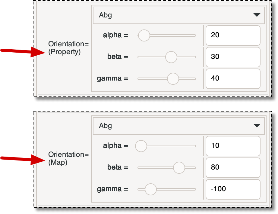
Two views of the Orientation panel in the Pixel Info Toolbox, pointing out where it indicates whether the orientation information comes from an
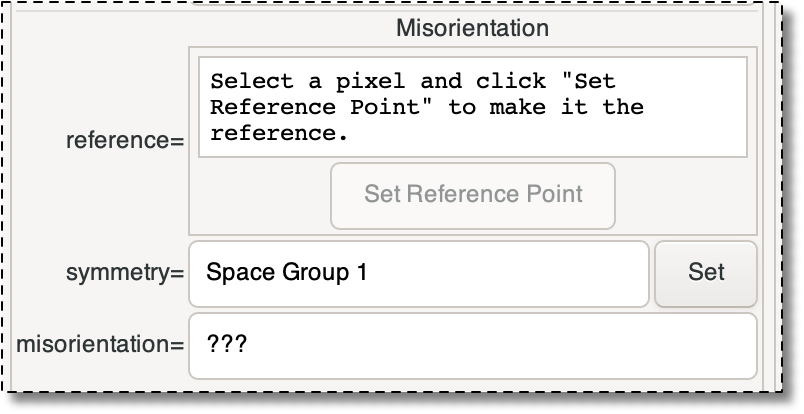
OrientationProperty(top), or an orientation map (bottom). Misorientations. The bottom section of the Pixel Info Toolbox computes misorientations between two pixels — the reference point and the current point. Misorientations can be computed between any two pixels in the
Microstructureas long as the pixels have anOrientationproperty or theMicrostructurecontains an orientation map.When you first open the Pixel Info Toolbox, the Misorientation pane looks like Figure 4.8.
To compute a misorientation, follow these steps:
-
Click on the reference point in the Canvas. Nothing will happen in the Misorientation pane, but if the pixel has an orientation, it will be displayed in the Orientation pane.
-
Click in the Misorientation pane to set the reference point to the point chosen in step 1. The position and orientation of the reference pixel will be displayed, as shown in the left side of Figure 4.9. You can change representation used for the angles, you can't otherwise edit the values in the toolbox directly.
The reference pixel is indicated on the Canvas by adding short diagonal segments to its outline, as shown in Figure 4.9 The color and width of the outline is determined by the
PixelInfoDisplay. -
Click on a different pixel in the Canvas. If that pixel has an orientation, the misorientation between it and the reference pixel will be displayed at the bottom of the Misorientation pane. The misorientation is calculated assuming that both points have the same crystal symmetry. To change the symmetry, use the button. (This does not affect the material properties — it only changes the displayed misorientation.)
-
To change the queried pixel, simply click on the Canvas again. To change the reference pixel, click on the pixel in the Canvas, and then click again. To clear the reference pixel, use the button at the top of the toolbox.
Figure 4.9. Misorientation
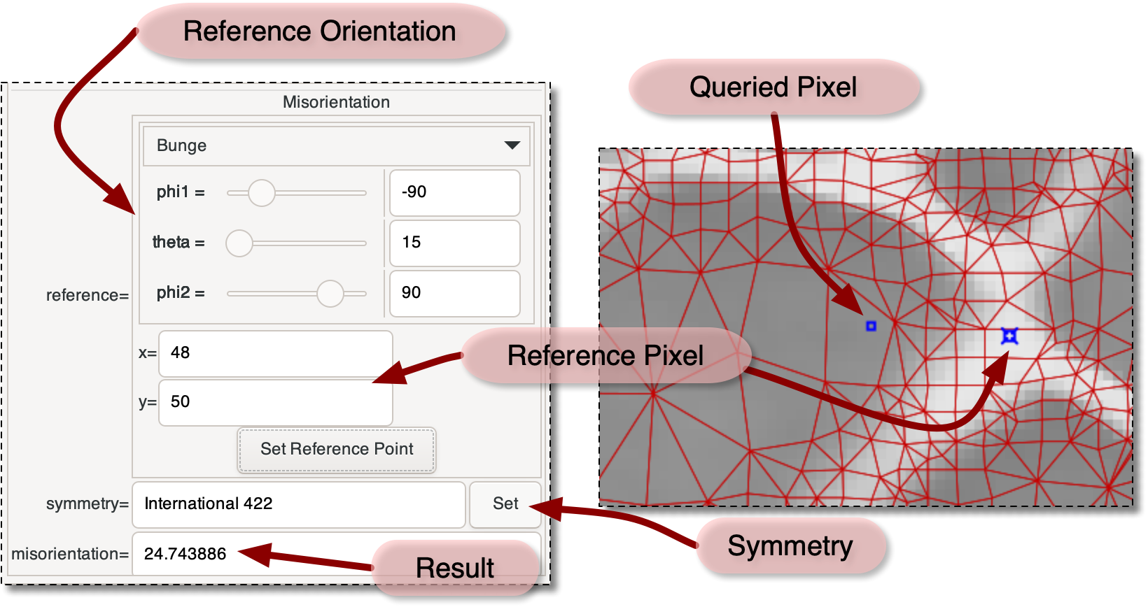
The Misorientation pane of the Pixel Info Toolbox (left), and a section of the Canvas (right) showing a queried pixel and a reference pixel.
-
|
|
 |
|
| 4.5. Toolboxes |  |
Chapter 5. Auxiliary Windows |