OOF2: The Manual
Edge boundary from nodes (EdgeFromNodes) |
||
|---|---|---|

|
6.5.2. Subclasses |  |
Name
Edge boundary from nodes (EdgeFromNodes) — Construct an edge boundary from a collection of nodes.
Synopsis
EdgeFromNodes(group, direction)
Details
-
Base class:
BoundaryConstructor -
Parameters:
group- Node group from which to deduce segments Type: The name of a node group, or
the placeholder
selection, referring to the currently selected nodes. direction- Direction of Boundary. Type: An object from the
Directorenumerated class.
Description
EdgeFromNodes is a BoundaryConstructor, used as the
constructor argument of the OOF.Skeleton.Boundary.Construct command when
building Skeleton boundaries. It
creates Edge
Boundaries from the currently selected Skeleton
Nodes or from a group of Nodes.
The Nodes are specified by the group parameter,
which must be either the name of a Node group or the special placeholder object,
selection.
Edge boundaries must be constructed from a single contiguous
non-branching set of Segments. To create an edge boundary,
therefore, OOF2 must be able to find a unique path from Node to
Node along the Segments joining them, passing through all of the
selected Nodes exactly once. This is a version of the Hamiltonian path problem, which is
NP-complete. That means that solving it is computationally
expensive when the number of Nodes is large. However, if the
selected set is not too large and is more or less linear
(i.e, it defines a reasonable
boundary) then OOF2 will be able to find the path quickly.
Not all sets of Nodes define a set of Segments, and some sets of
Nodes can define more than one set of Segments. In those cases,
EdgeFromNodes will fail and no boundary will
be defined. In the GUI, the button in the
dialog box will be disabled if the Nodes don't define exactly one
linearly connected set of Segments. See Figure 6.74 to
Figure 6.78 for some examples of
configurations that do and do not define edge boundaries.
Edge boundaries must be directed. Boundary
conditions use the direction to determine the boundary normal
and the direction of applied Fields and Fluxes. The
direction parameter specifies the direction of
the boundary being created. The legal values for
direction depend on the topology of the boundary
being constructed. When the Segments form a closed loop, the legal
values are 'Clockwise' and
'CounterClockwise'. When the Segments form an
open line or curve, the values are 'Left to
right', 'Right to left',
'Top to bottom', and 'Bottom to
top'. OOF2 compares the positions of only the first
and last Nodes when determining the direction of an open boundary.
EdgeFromNodes will always create a closed
boundary if the set of Nodes allows it. To create an open
boundary from a set of Nodes that also defines a closed boundary,
first create the closed boundary and then use OOF.Skeleton.Boundary.Modify to remove one or
more Segments from it.
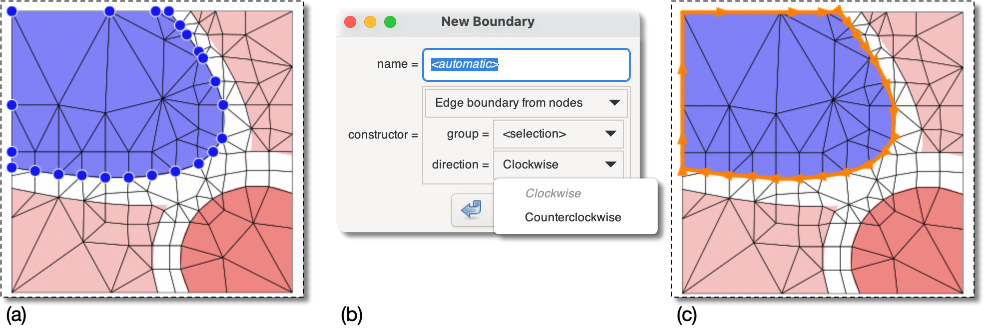
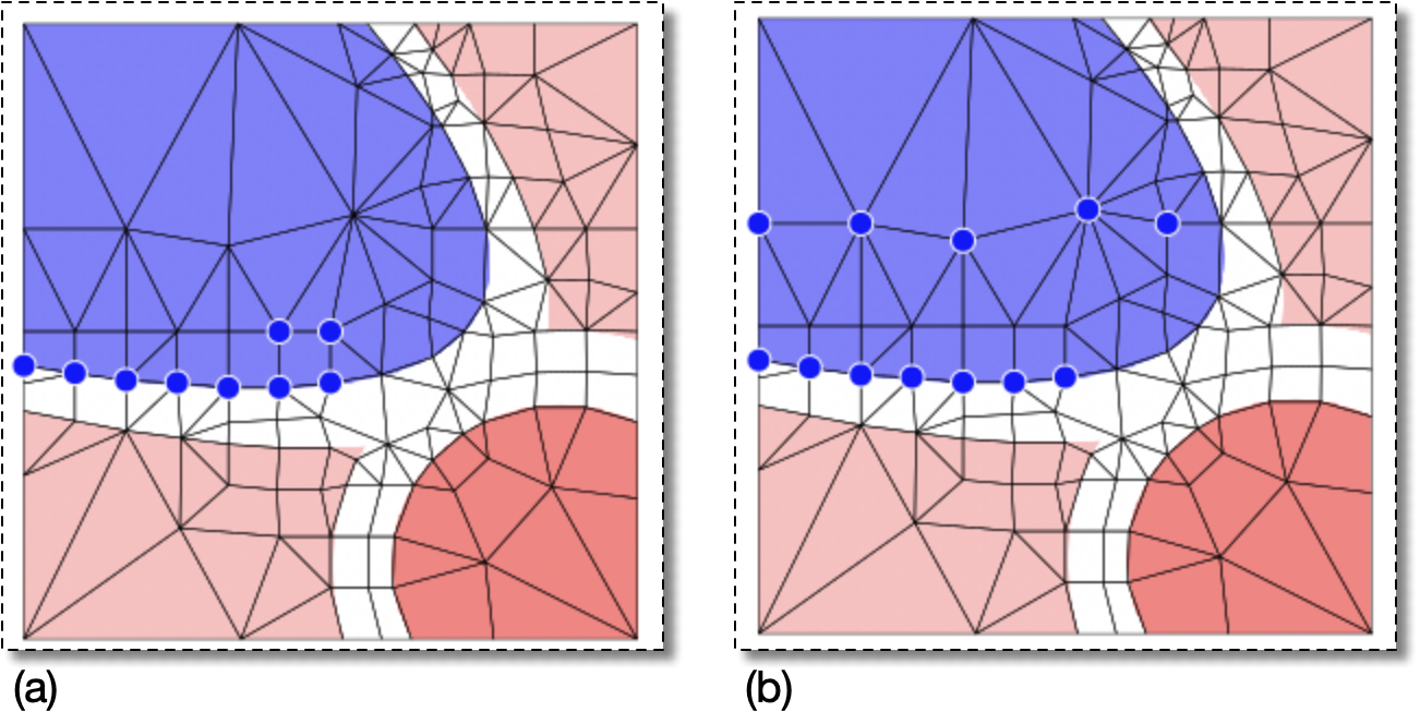
Figure 6.75. Constructing an Open Edge Boundary from Nodes
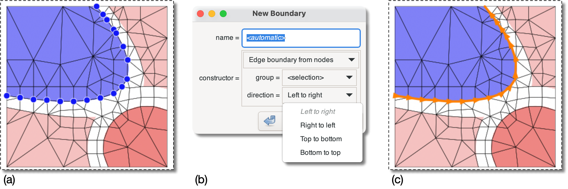
(a) The selected Nodes do not form a closed loop,
but they can be linked into an open path …
(b) … so the choices for direction
are 'Left to right',
etc.
(c) The boundary that would be constructed by choosing
'Left to right' or 'Buttom
to top' in (b).
Figure 6.76. Failing to Construct an Edge Boundary
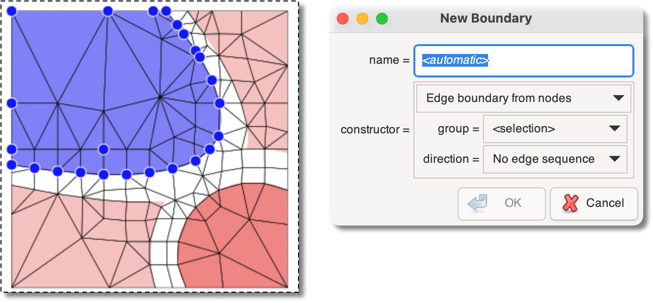
Adding a single Node to the selection in Figure 6.74 makes it impossible to
connect the Nodes with a non-branching set of Segments. No
boundary can be constructed. The dialog box says “No
edge sequence” and the button
is disabled.
Figure 6.77. Constructing an Edge Boundary Again
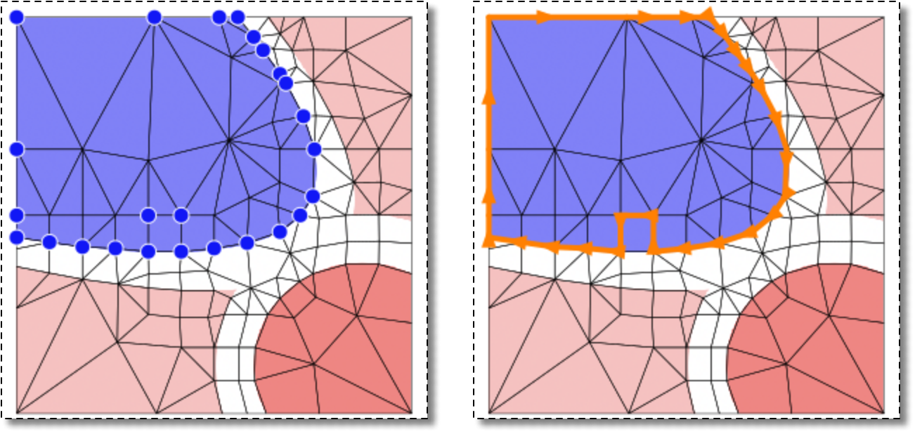
Adding yet another Node to the selection in Figure 6.76 makes it possible to
construct a path through all the Nodes again.
|
|
 |
|
Edge boundary from elements (EdgeFromElements)
|
 |
Edge boundary from segments (EdgeFromSegments) |