OOF: Finite Element Analysis of Microstructures
Table of Contents
Here are a few step-by-step examples that will help get you started with ppm2oof.
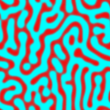
This example assumes that ppm2oof has been downloaded and can run on your local machine and that you have also downloaded the example .ppm file spinodal.ppm, shown in Figure 2.1. spinodal.ppm. This image was produced by a simulation of spinodal decomposition.
This example is designed to illustrate various useful features of ppm2oof.
-
Start ppm2oof: Start up ppm2oof and load the image by typing ppm2oof -file spinodal.ppm. Two windows will be placed on the screen. [9] They are the Drawer with the default Display dashboard and the ppm2oof Main Menu. The drawer should have a visible image in it that is the same size (in pixels) as the original image.
If you don't get this then you probably don't have ppm2oof installed properly or there is a hardware conflict.
-
Resize: To resize the image in the drawer, click on the word Display and select the Coordinates dashboard from the pull-down menu. In the Coordinates dashboard, find and click on the Fit to Window button. The image should now fill the drawable part of the drawer. If you wish, experiment with the magnification by left/middle/right clicking on the z button in the upper-left corner of the image--and play with the scroll bars below and to the right of the z when the image is larger than the window in which it is drawn. Notice that middle-clicking on z has the same effect as Fit to Window.
-
Select Pixels of One Phase: Select the Select dashboard, by clicking on the word Coordinates and selecting Select from the pull-down menu. You will see a list of functions associated with methods of identifying groups of pixels. Highlight the radio button Demography to signal that mouse clicks on the image should identify all pixels that are similar to the pixel that was selected.
To define which pixels should be included, click on the parameters button of Demography. You should see a new window appear on the display--this is the function window for the Demography function. Set the plus_or_minus value to 120. By either hitting a carriage return or by clicking on the function name (in this case Demography), you will see another new window appear on the display--this is the Message Window. The message box tells you that a change has taken place and keeps track of the entire session.
Use the mouse to move the cursor over one of the two phases and click--you should observe that all the similar pixels have changed color. Here ``similar'' means all pixels whose equivalent gray value is within 120--the number you set in the function window--of the gray value of the pixel you clicked on. The changed color indicates that those pixels are now part of the selected set. Notice how clicking in different regions give you different selections. Click in the middle of a red region to select all the red pixels.
-
Set Material Properties: Find the /materials submenu in the main (or root) ppm2oof menu and click on that menu item. You should notice that the Materials submenu replaces the root menu. The middle column of the Materials submenu is a list of functions; in this case those functions are materials. Executing one of these functions will set the material properties for the selected pixels. Click on the isotropic material function to bring out a fill-out table for the isotropic material parameters. [10] For this example, set the gray = 0.8, set planestrain to true, Young's modulus young = 10, Poisson's ratio poisson = 0.33, and the coefficient of thermal expansion alpha = 1e-6. (Use a tab or the mouse to skip between the parameters. Hitting a carriage return in any field executes the function, as does a click on the function name.) When you have finished filling out the function table, click on the function name (isotropic) to associate the selected pixels with the material properties that you have specified.
-
Select the Second Phase: The current selected group should have its material properties specified. To specify the material properties of the pixels associated with the other phase, those pixels must become the current selected set.
In the Select dashboard of the graphics drawer, click on the Invert button and the current selection becomes the complement of the previous pixel selection--this is the second phase.
-
Set Material Properties for the Second Phase: As before, click on the isotropic function in the /materials menu. Set the parameters for the second phase: gray = 0.2, planestrain to true, young = 1, poisson = 0.33, and the coefficient of thermal expansion alpha = 3.2e-6.
After executing this function, material properties have been specified for the entire image.
-
Observe: To view the material image instead of the input image, first clear the current selection by clicking on the Clear button in the Select dashboard of the graphics drawer. From the Display dashboard, switch the radio button from Image to Material and the materials should be displayed. [11] The Image/Material choice made on the Display dashboard applies to the other dashboards.
Switch to the Pixel dashboard in the graphics drawer. Click [12] on a pixel in the image to see what material was specified for that pixel. The information for the queried pixel appears in the dashboard.
-
Create an Initial Mesh: Click on the Home button on the ppm2oof menu-window (or use the Home button on your keyboard if that's easier to find), and then select the /adaptive_mesh submenu. Bring up the function parameter window for the function /adaptive_mesh/create in the middle column by clicking once on the word create. The create window allows you to specify the initial mesh. Create a fairly coarse uniform initial mesh by selecting nx=30 triangles along the bottom border and ny=30 triangles along the side border.
-
Observe: Select the Display dashboard of the graphics drawer. Notice that the show by triangle option is now available because a mesh of triangles was created in the previous step. Set the display to show the triangles of the mesh instead of the pixels of the material image.
Notice that the mesh structure is reminiscent of the material image, but is too coarse to duplicate it exactly. Switch between the triangle display and the pixel display a few times (switch an even number so that triangles are displayed for the next step) and notice how the material properties in the image are inherited by the mesh triangles. Pay special attention to the triangles that cover materials of both types.
If you had selected values for nx and ny in the previous step such that each pixel in the image was divided along one of its diagonals into two mesh triangles, then the mesh structure would duplicate the underlying image exactly. However, this usually is a waste of resources. The uniform mesh can be adapted to the material image. The mesh adaptation strategy should try to minimize the heterogeniety of material properties within the triangle (i.e., each triangle should lie in one material only) and the triangles should be as equilateral as possible so that they perform as good numerical interpolates in subsequent calculations. To maximize homogeneity, the material interfaces should lie on the edges of the triangles.
The mesh quality can be quantified. This quantification can be observed in the Mesh dashboard in the graphics drawer. Switch to the Mesh dashboard, ensure that the ? button is pushed, and click the mouse on a few of the elements. The energy (E) values that are displayed in the dashboard refer to the character of the triangular element that is being selected. Eshape is a measure of how much the triangular element differs from being equilaterial--this quantity is minimized and equal to zero when the triangle is equilateral. Ehomog is a measure of homogeneity of the element and is minimized with a value of zero when the interior of the triangle is composed of a single material. Click on a few triangles so that you develop some intuition about how the homogeniety energy behaves--it may be instructive to put the display back into pixel mode (with the Display dashboard) and to zoom in (with the Coordinates dashboard) as you do this. Because all of the triangles are the same non-equilateral shape, the shape energy has the same positive value for each element. The E value is a linear combination of the homogeniety energy and the shape energy of an element:
 .
The mesh
adaptation process minimizes a "cost
function" that is the sum of the E's for each
element. The default weighting factor
.
The mesh
adaptation process minimizes a "cost
function" that is the sum of the E's for each
element. The default weighting factor
 is 0.33 and can be changed
in the Variables column of the /adaptive_mesh submenu. The value of
determines how the mesh
adapts--setting to 1
will result in homogeneous meshes but will not penalize
long skinny triangles, while setting
to 0 will tend to
produce equilateral inhomogeneous triangles.
is 0.33 and can be changed
in the Variables column of the /adaptive_mesh submenu. The value of
determines how the mesh
adapts--setting to 1
will result in homogeneous meshes but will not penalize
long skinny triangles, while setting
to 0 will tend to
produce equilateral inhomogeneous triangles.
-
Manual Mesh Apaptation: Using the Mesh dashboard (with the mouse action set to "query" mode by clicking on the ? button), locate and select a relatively high E element--you probably will find one that straddles a material interface. Set the mouse to "move node" mode by clicking on the button with the double-headed arrow. Click on one of the nodes and drag it around. Notice that the display changes--while you are moving a node, the display shows the relative change in E for all triangles that share that node. You can move the node "out of the element" by pushing it through it opposite side, but ppm2oof will reject any attempt to create an element with negative area. See if you can minimize the the element's E manually.
-
Automatic Mesh Apaptation: Manual mesh adaptation is useful when you can see that a particular node is poorly placed. However with a large number of nodes, this would soon become wearisome. For this reason, we have included several ways of automatic adaptive mesh refinement.
There are two methods of mesh improvement by moving nodes: the first (and faster) method, /adaptive_mesh/anneal, tests the change in energy by moving nodes at random and accepts or rejects the move based on a Boltzmann probability function (similar to simulated annealing~\cite{NumericalRecipes}); the second method, /adaptive_mesh/relax, tries to move the nodes in the optimal direction by evaluation of spatial derivatives at each node. [13]
Try to improve the mesh by executing (single-clicking) the /adaptive_mesh/anneal function. You will want to rerun this function, so click on the Freeze button so the function window remains on the display. Let delta=1, iterations=20, and T=0 and execute. Notice how the nodes tend to move towards the material interfaces just where we would expect them to accumulate in an optimal mesh.
Another method of improving the mesh is to refine (i.e., subdivide) those elements that have large E values. Navigate to the /adaptive_mesh/refine submenu. Single-click on the E function to refine those elements with have a large E. Click on the Freeze button and execute the function. Notice how the elements at the interface tend to subdivide while those in homogeneous regions tend not to subdivide. Since this mesh does not yet have very many homogeneous elements, it can be hard to see which ones have not been divided. Use the undo and redo commands in the /adaptive_mesh/stack submenu to flip back and forth between the refined and unrefined meshes to help see exactly what /adaptive_mesh/refine/E did.
Experiment with the /adaptive_mesh/swap_worst command. When two adjacent triangles form a quadrilateral, and when E can be reduced by replacing those two triangles with the two formed by flipping the diagonal of the quadrilateral, then swap_worst} does so. It operates on the triangles with the worst (highest) E first. It is usually beneficial to introduce a few /adaptive_mesh/anneals and /adaptive_mesh/swap_worsts [14] between refinements.
It is also a good idea to save (see next step) intermediate meshes as they begin to look tolerably decent. If you run out of memory by trying to refine too many times and create more elements than you have RAM for, the system will step in and crash the program before it can mesh up any further.
Notice that if you refine the mesh too much, two things happen. First, the program gets very slow, as it's keeping track of more triangles. Second, the mesh boundaries begin to get jagged (set show by triangle and unset Mesh in the Display dashboard to see this clearly) as the triangles begin to resolve the individual pixels in the material image. This is a sign that your mesh is too fine.
-
Save the Mesh: The mesh and its material properties are saved to disk in a special format called a goof file (grid for oof). This file can be read directly by ppm2oof's companion program oof or converted to a different format by one of the convenient converters that are also available on the OOF website.
To save the goof file, navigate to the /adaptive_mesh menu and single-click the save function. [15] You will find a text area at the bottom of the function window for you to name the file just about anything you wish. We tend to use names ending in .goof, but we're pretty irreverent. [16]
-
Quit.
This entire example can be run by starting the program with the flag -start example1.log.
You may wish to edit this startup file or rerun the example and try out a few of the other functions that appear on the screen, you haven't already.
[9] On SGI computers, don't try to resize the windows as they are being placed--if you want to resize them, do it after they have been successfully placed. This is due to a bug either in the SGI window manager or the XForms library. In either case, we can't fix it!
[10] Details about the materials, their behavior, and their units (i.e, scaling) are described in the oof manual.
[11] Note that the show by triangle sub-radio button is not available, this is because no mesh currently exists.
[12] The cursor should look like a "?". The pixel being queried lies under the "." of the "?".
[13] Actually, this method has never worked well for us. We suspect a bug in the code, but since the annealing technique works so well, we've never bothered to sort out what's wrong with the relaxation routine.
[14] And if you are going out for swapworsts, could you bring a couple? Mustard and relish please. Thanks.
[15] Don't get confused by the Save button below the dashboard area on the graphics drawer--that function is for saving the current image in a .ppm file.
[16] As you may have noticed. We're also pretty punchy. The first draft of this manual was written in the air during a weekend jaunt from Boston to Singapore and back.


