OOF2: The Manual
| Neumann (NeumannBC) | ||
|---|---|---|

|
6.5.2. Subclasses |  |
Name
Neumann (NeumannBC) — Set the normal component of a Flux (eg, stress, heat flux) along the boundary.
Synopsis
NeumannBC(flux,profile,boundary,normal)
Details
-
Base class:
BC -
Parameters:
flux- Flux whose value is specified across this boundary. Type: A
Fluxobject. profile- Profiles describing the prescribed flux. Type: A FluxProfileSet object, or a list of
ProfileXTs, or a singleProfileXT. boundary- Edge boundary to which this condition applies. Type: The name of an edge boundary in a mesh.
normal- If true, the boundary condition is given in a local right-handed coordinate system where x is the outward normal to the boundary and y is the tangent direction. If false, x and y are lab coordinates. Type: Boolean, 0 (false) or 1 (true).
Description
Neumann boundary conditions apply the normal component of a Flux
on a boundary. (In
mathematics, Neumann conditions usually fix the normal derivative
of the unknown field at a boundary. In OOF2, Fluxes are
proportional to the derivatives of Fields, so we've appropriated
the term “Neumann”.)
Neumann boundary conditions only apply to Edge
boundaries. An edge boundary is composed of a directed series of
segments, and this direction determines the definition of the
positive normal. If a boundary goes counterclockwise around the
perimeter of a Skeleton, then its normal points outward. That is,
the unit vectors in the normal and tangent directions form a right
handed coordinate system (see Figure 6.87).
Neumann boundary conditions are integrated over element edges, and are therefore insensitive to node density. That is, adding nodes to a boundary without changing the boundary condition will not change the effect of the boundary condition. Compare this to Generalized Force boundary conditions, which are applied node by node and are sensitive to node density.
The profile parameter specifies the value of
the normal component of the Flux along the boundary. The
profile is divided into a number of components
depending on the dimension of the Flux. If the Flux is a
vector (e.g, heat flux) then its
normal component is a scalar, and only one profile,
p0, must be provided. If the Flux is a
tensor flux (e.g, stress), then its
normal component is a vector, and two in-plane profiles,
p0 and p1, must be provided.
Profiles may be arbitrary functions of position, and are specified
by providing a ProfileXT object.
See FluxProfileSet for details on how to
specify multiple Profiles.
The normal parameter specifies how the profile
components are to be interpreted when the flux normal is
multidimensional. If normal is
false, then p0 and
p1 are the x and y components of the flux
normal in the lab coordinate system (x towards the right, y
towards the top). If normal is true, then
p0 and p1 are the components
of the flux in a local coordinate system with
p0 normal to the boundary and
p1 tangent to it. This coordinate system
changes from point to point on the boundary if the boundary is
curved. When the flux normal is a scalar, the
normal parameter is ignored.
Figure 6.87. The Normal Direction for an Edge Boundary
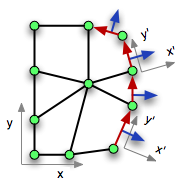
The red arrows joining nodes form an edge boundary. The blue arrows perpendicular to them are in the positive normal direction. The axes labelled x and y are the “lab” axes. The axes labelled x' and y' are the local “normal” axes.
|
|
 |
|
| Named Analysis (NamedAnalysisOutput) |  |
Newton (Newton) |