OOF2: The Manual
| OOF.Graphics_n.Layer.New | ||
|---|---|---|

|
6.2. Menus |  |
Name
OOF.Graphics_n.Layer.New — Add a new graphics layer.
Synopsis
OOF.Graphics_n.Layer.New(category, what, how)
Details
- Parent Menu: OOF.Graphics_n.Layer
-
Callback: function
GfxWindow.newLayerCBin moduleooflib.common.IO.ghostgfxwindow -
Parameters:
category- The kind of object to display. Type: The name of a class of OOF2 objects (eg,
'Microstructure'or'Skeleton'). what- The object to display. Type: The path to an OOF2 object.
how- How to display the object. Type: An object of the
DisplayMethodclass.
Description
A Layer is added to a Graphics Window by invoking the menu
Layer/New command in the window's menu
bar. This runs the OOF.Graphics_n.Layer.New command. Figure 6.8 illustrates the dialog box corresponding
to the command.
There are three parameters which define a graphics Layer:
-
category— The type of object being displayed. This includes the objects defining the simulation (Skeleton,Image, etc), as well as some special objects (the pixel selection and the top bitmap). -
what— The path to the actual object being displayed, which is an object of the givencategory, or a proxy. -
how— TheDisplayMethodby which the object will be displayed.
Figure 6.8. The New Graphics Layer dialog
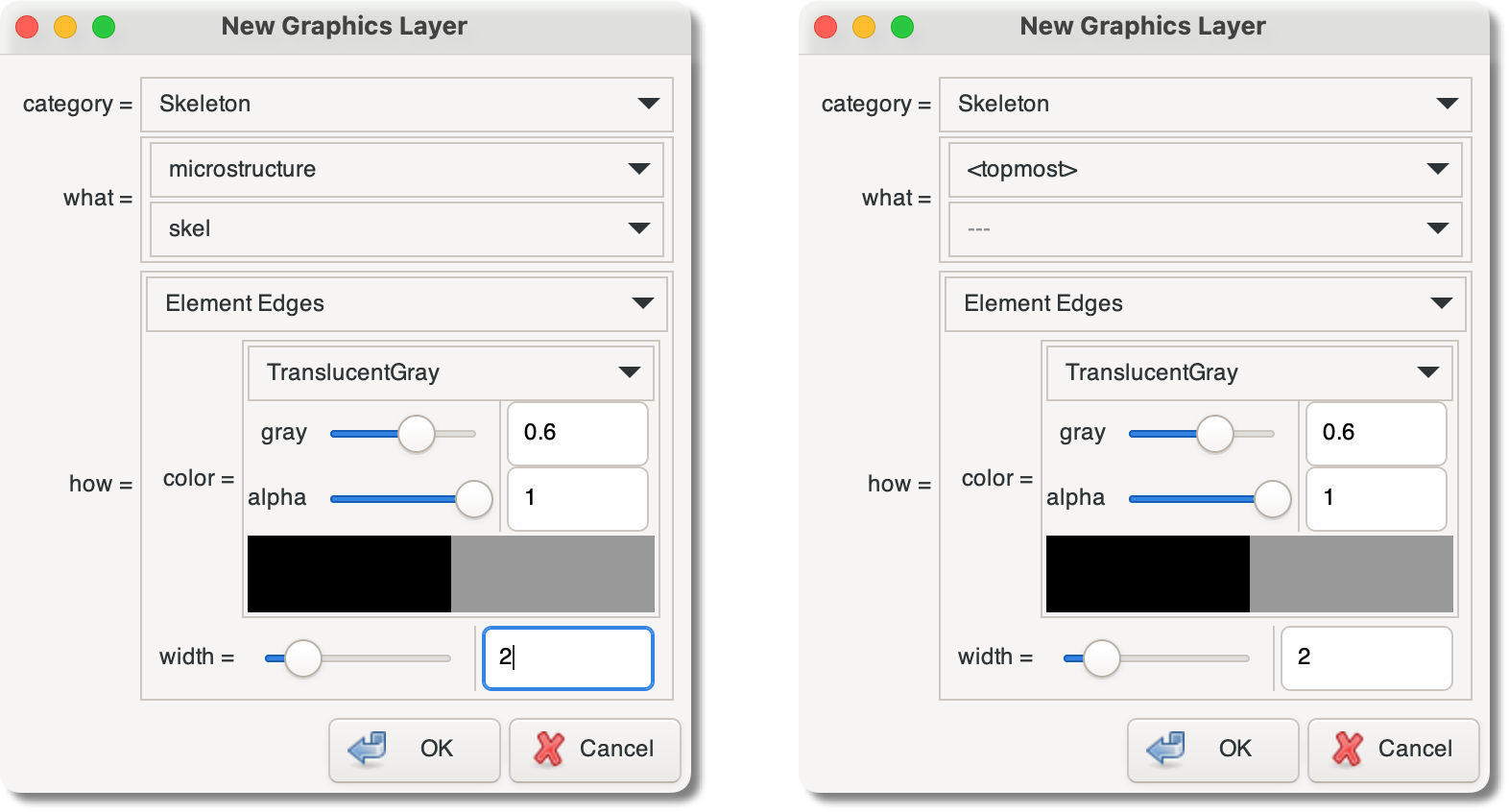
Two views of the New Graphics Layer
dialog. category is set to
Skeleton. The three boxes labelled
category, what, and
how define the new Layer. The dialog on
the left is creating a Layer that will explicitly display
the Skeleton whose path is
microstructure:skel. The dialog on the
right is creating a Layer with the proxy
<topmost>, implicitly referring
to the Skeleton used in the topmost explicit Layer.
In the New Graphics Layer dialog, the
pull-down menus for what and
how change according to the current
category setting. The
what menu lists the existing objects in the
category, and the the how menu lists the
DisplayMethods that are
capable of displaying them.
The parameter what can be explicitly set to the
path to an object. It
can also be set to a proxy object, which
implicitly defines the Layer by referring to another Layer in
the display. In the dialog box, the proxies appear in the
first pull-down menu in the what section, in the
form of characters enclosed in angle brackets
(e.g,
<topmost> or <top
bitmap>).
The available proxies depend on the current
category. They are:
<topmost>— the object in the topmost non-proxyLayerthat can be displayed by the selectedDisplayMethod.<top bitmap>— the object in the topmost non-proxyLayerthat is being displayed as a bitmap.<contourable>— the object in the topmost non-proxy layer; that contains data that can be displayed as a contour plot.<top activearea>— the Active Area of theMicrostructurein the topmost non-proxyLayerthat is displaying aMicrostructure.<top microstructure>— theMicrostructurein the top non-proxyLayerthat is displaying aMicrostructure.
When proxies are used in scripts, they appear as simple quoted strings, with the angle brackets included, e.g:
      OOF.Graphics_n.Layer.New(
          category='Skeleton',
          what='<topmost>',
          how=SkeletonEdgeDisplay(color=TranslucentGray(value=0.6,alpha=1),width=2))
Proxy objects are heavily used in the predefined Layers
contained in every new Graphics Window. They are used, for
example, to show the selected pixels in the topmost Microstructure or
Image, or the selected Elements in the topmost Skeleton.
|
|
 |
|
| OOF.Graphics_n.Layer.Hide |  |
OOF.Graphics_n.Layer.Reorder_All |