OOF: Finite Element Analysis of Microstructures
Next: How to Read this Up: Introduction Previous: The OOF Project Contents
The OOF Program
OOF is a finite element solver designed to operate on data structures which come from images. The image may be a scanned micrograph of a composite material, a satellite image of the earth, the result of a computer simulation, or a hand drawn sketch. Currently OOF performs microstructural thermoelastic calculations in two dimensions while averaging over the out-of-plane direction with plane stress or plane strain.
OOF works in tandem with a second program, called PPM2OOF[1], which creates the data file for OOF by graphically combining data from an image1.2with user-specified properties. We will use the term microstructure to refer to the image and the associated spatially-correlated properties. PPM2OOF creates the data representing the microstructure; that data is saved in a file--called a .goof file (``grid for oof'')-which is the starting point for an OOF calculation.
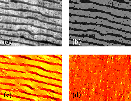
A few examples may clarify the purpose of OOF. OOF can be used to calculate the distribution of stresses in a laminar microstructure taken from a digitized optical micrograph (such as the one in Figure 1.1a). After PPM2OOF assigns material properties to the image, creates a finite element mesh, and writes the mesh to a file (the .goof file), OOF can be used to perform a variety of virtual mechanical tests to investigate the behavior of this microstructure. For example, in Figure 1.1 the image with its correlated properties was tested in two uniaxial strain states (the horizontal and vertical edges were each displaced normal to themselves) by the specification of boundary conditions in OOF. The elastic equilibrium solution was numerically calculated. Graphical representations of the solution for two separate components of the stress are illustrated in Figure 1.1. It is clear that that stress parallel to the layers is concentrated in the layers, whereas stress perpendicular to the layers is uniformly distributed.
 |
As a second example, consider a simple bi-material, such as that found in some thermostats, where one material expands more than the other as temperature increases. Suppose you drew the picture in Figure 1.2 and saved a scan of it in some graphics file (or, as we did to create this example, simply used a computer drawing program).
 |
 |
If you wanted to know how the material will deform as the temperature increases, you would simply import the mesh into OOF via the .goof file, specify the change in temperature with a few clicks and keystrokes, and calculate a solution with one more click. Figure 1.4 illustrates the elastic energy density in the deformed bi-material.
 |
You might also ask how the shear stress would be distributed if the bi-material were fixed to a rigid substrate (finite in the horizontal direction and either thin (plane stress) or very thick (plane strain) in the out-of-page direction). OOF lets you set the appropriate boundary conditions and solve for the stress, as shown in Figure 1.5.
 |
Subsections
Next: How to Read this Up: Introduction Previous: The OOF Project Contents /* Send mail to the OOF Team *//* Go to the OOF Home Page */