µMAG Standard Problem #4 results
See the problem specification.
Disclaimer
µMAG could not succeed without the contributions
of colleagues working outside NIST. Although we value the
contributions made by these colleagues, NIST does not necessarily
endorse the views expressed or the data presented in the submitted
solutions shown below.
Solution directory
-
Comparisons
- G. Albuquerque,
J. Miltat and A. Thiaville
-
R. D. McMichael, M. J. Donahue, D. G. Porter, and
J. Eicke
-
Liliana Buda, Lucian Prejbeanu, Ursula Ebels and Kamel
Ounadjela
-
E. Martinez, L. Torres and L. Lopez-Diaz
-
José L. Martins and Tania Rocha
-
P.E. Roy and P. Svedlindh
-
Massimiliano d’Aquino, Claudio Serpico,
and Giovanni Miano
-
Dmitri Berkov
-
M. J. Donahue and D. G. Porter
-
Rasmus Bjørk, E. B. Poulsen and A. R. Insinga
Submitted Solution:
R. D. McMichael, M. J. Donahue, and D. G. Porter
- Date:
- September 27, 2000.
- From:
- R. D. McMichael, M. J. Donahue, and D. G. Porter.
National Institute of Standards and Technology, Gaithersburg, MD
20899
J. Eicke
Institute for Magnetics Research,
George Washington University, Washington, DC 20052
- Contact:
- Bob McMichael
We used the OOMMF public
code to compute solutions to standard problem #4. The mesh was a 2D
square grid with 3D spins interacting through the exchange
interaction and magnetostatic fields. Magnetostatic energy was
computed under the assumption that the magnetization was uniform
within each cell, and the field due to the magnetostatic charges at
the cell boundaries was averaged over each cell. Except where noted
below, the exchange energy was calculated using a "eight-neighbor dot
product" representation. The maximum time step was set at 0.2 ps, but
smaller time steps are taken when necessary to keep the error within
certain bounds. See the OOMMF documentation for
mmsolve for details on the solver.
Results:
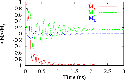
- For the first part of the problem, with the field applied
170° from the x-axis (Field 1), we used 2.5 nm cell size
and maximum time steps of 0.2 ps. The maximum angle between
neighboring spins on the lattice was 22.3° at 0.298 ns.

a plot of the spatially averaged magnetization

and an image of the magnetization when Mx
first crosses zero.
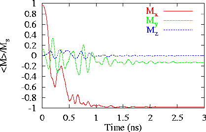
- For the second part of the problem, with the field applied
190° from the x-axis (Field 2), we initially used 2.5 nm
cell size and a maximum time step of 0.2 ps. The maximum angle
between neighboring spins on the lattice was 71.9° at 0.571 ns.
For comparison, using slightly larger 3.125 nm cells, the maximum
angle was 118°. Finally, the results shown below are from a
calculation done with 3.125 nm cells using a "four-angle" exchange
energy representation. The four-angle representation is based on the
assumption that the magnetization rotates uniformly between spins.
Under this assumption, the exchange energy is proportional to the
square of the angle between neighboring spins. Unlike the dot product
representation, the four-angle has the property of providing an
increasingly stronger aligning torque as the angle between spins
increases up to 180°. Using the four-angle representation, the
maximum angle between spins was 48.1°. [M. J. Donahue and
R. D. McMichael, Physica B 233, 272
(1997).]

A plot of the spatially averaged magnetization calculated with 3.125
nm cells and the four-angle exchange representation.

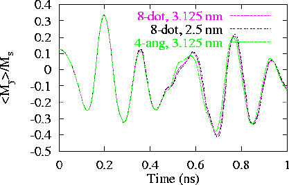
Plots of M_y
calculated with 3.125 nm and 2.5 nm grids using the eight-neighbor dot
product exchange representation and with a 3.125 nm grid using the
four-angle exchange representation.

and an image of the magnetization when Mx
first crosses zero.
Raw data:
Please note that the following data follows a coordinate system
that is rotated 90° from the specified coordinate system. Vector
data is in the ovf
format.
Please send comments to [email protected] and join the
µMAG discussion e-mail list.
Site Directory
µMAG organization / NIST CTCMS /
[email protected]
11-NOV-2021


