OOF2: The Manual
| Snap Nodes (SnapNodes) | ||
|---|---|---|

|
6.5.2. Subclasses |  |
Name
Snap Nodes (SnapNodes) — Move nodes directly to pixel boundaries.
Synopsis
SnapNodes(targets,criterion)
Details
-
Base class:
SkeletonModifier -
Parameters:
targets- Which elements to snap. Type: An object of the
SnapNodeTargetsclass. criterion- Acceptance criterion. Type: An object of the
SkelModCriterionclass.
Description
SnapNodes moves Nodes to improve the
Elements' Homegeneity Energy.
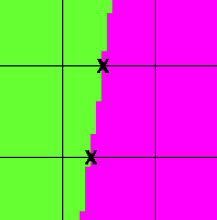
If an Element edge crosses over regions of the Microstructure belonging to
different pixel categories, then
SnapNodes tries to move one of the Element
corners to the crossing point. These points are called
“transition points”, and are illustrated in Figure 6.101.
The general procedure for snapping Nodes is as follows.
-
Scan the current
Skeletonto find candidateNodesfor snapping. The candidates are identified by thetargetsparameter. -
Loop over the
Elementscontaining snappable nodes, and identify the transition points along eachSegmentof eachElement. -
Find all possible snaps involving one or two
Nodesof a singleElement, assigning a priority to each according to the arrangement of its transition points. The priorities are listed in Table 6.5. -
Starting with the highest priority snaps (and choosing randomly from snaps with equal priorities) attempt to actually move the nodes. The move is accepted or rejected according to the given
criterionparameter. When more than one snap is possible for oneElement, all are attempted and the best is chosen. After successfully snapping theNodesof anElement, the nodes of any neighboring snappableElementsare attempted, regardless of their priority.[35]
Because snaps with the same priority are attempted in a random
order, undoing
and repeating a SnapNodes operation may not
reproduce the original result. For the same reason, repeating
(without undoing) a SnapNodes operation may
move Nodes that weren't moved the first time.
Table 6.5. Snapping Nodes
| Element Type | Quadrilateral | Triangle | |||
|---|---|---|---|---|---|
Priority |
1 | 2 | 3 | 1 | 2 |
| Type |
 |
 |
 |
 |
 |
| Possible Snaps |
 |
 |
 |
 |
 |
 |
 |
 |
 |
||
 |
|||||
Here's a simple example of snapping nodes of heterogeneous
elements. Figure 6.102 shows a Skeleton
that features some heterogeneous elements. The resulting Skeleton
(after applying SnapNodes with α=1.0)
is shown in Figure 6.103. The material
boundaries have been resolved nicely, although many badly shaped
elements have been created. This is because the procedure was
performed with α=1, which emphasizes homogeneity
and ignores shape.
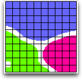
Figure 6.103. After Snapping Nodes with α=1.0
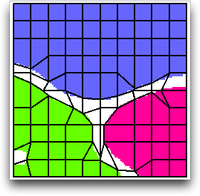
After snapping nodes. All of the elements are still quadrilateral, although some have very short sides or corner angles of nearly 180°.
Snapping Nodes (like all Skeleton modifications) tends to produce
badly-shaped elements when done with large values of α.
However, SnapNodes is really a homogeneity
oriented operation, and works best when given a large α. It's
usually best to allow it to create badly shaped Elements, and to
clean up afterwards by applying the Rationalize Skeleton modifier.
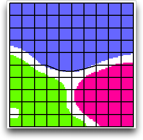
Figure 6.104 shows the same Skeleton, but
after snapping with α=0.7 instead of 1.0. The elements have a
much nicer shape, but very few nodes have been moved to material
boundaries.
|
|
 |
|
| Heterogeneous Elements (SnapHeterogenous) |  |
Snap Refine (SnapRefine) |