OOF: Finite Element Analysis of Microstructures
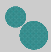
The second example uses the image file spots.ppm, shown in Figure 2.2. spots.ppm. It's a contrived example, contrived to illustrate some features of ppm2oof.
-
Start ppm2oof: Start ppm2oof by typing ppm2oof. Because you haven't loaded an image, only the Main Menu window appears on the screen.
-
Load the image file: Single click on the /ppmfile command. The /ppmfile function window appears on the screen. Click on the ? button to the right of the filename entry field. The FileSelector window appears. Navigate to the directory where spots.ppm.gz lives, if necessary. [17] Click on the filename, and press the Ready button, or double click on the name. The FileSelector disappears, and the file name appears in the filename field in the function window. Execute the function by pressing the ppmfile button at the top of the window.
The Message Window and Graphics Drawer appear.
If you found the FileSelector too clumsy, you could have typed the filename into the filename field directly.
-
Rescale the Image: Enlarge the image by clicking on the z button with the middle mouse button, or by choosing Fit to Window in the Display dashboard.
-
Select a Spot: Switch to the Select dashboard. Using the default selection method (Burn), click somewhere inside the smaller spot on the image. Notice that not all the pixels in the spot have been selected. Depending on exactly where you clicked, the Message Window should report that you either selected 1432 or 2378 pixels.
-
What went wrong? Not all the pixels were selected because the Burn algorithm selects contiguous pixels with similar colors, and the spots in the image consist of three colors which aren't similar enough. Find out what those colors are by switching to the Pixel dashboard, and clicking on the spot in the image. A few clicks (if you're lucky) will show you that the RGB values of the colors are [51, 135, 135], [51, 152, 152], and [67, 152, 152].
-
Try again: Switch back to the Select dashboard. Change the definition of similar by clicking on the Parameters… button next to Burn. Notice that the local_flmblty parameter is 10, which is less than 152-35, which is the largest difference between color components in the spot. Change both flmblty parameters to 20, and press the burn button. The next Burn will use the new parameters to measure similarity.
Repeat the burn, either by clicking on the spot in the image again, or by using the Repeat button on the dashboard. The whole spot is now selected.
-
Create Pixelgroups: From the /pixelgroups menu, single click on the new function and press the Freeze button on the function window. Create a new pixelgroups by typing spots in the name field and clicking on the new button. Create another pixelgroup by typing background and clicking new again. Close the function window with the Dismiss button.
-
Add Pixels to the Pixelgroups: In the /pixelgroups/add menu, double click on spots to add the pixels in the selected small spot to that group. In the graphics window, click on the larger spot to select it, and click again on spots in the menu. Click on the gray background in the image to select those pixels, and add them to the background pixelgroup.
-
Clear the Selection: In the Select dashboard, click on the Clear button.
-
Create a Mesh: Execute the menu command /adaptive_mesh/create with nx=10 and ny=10.
-
Change the Mesh Color: The default yellowish mesh is hard to see on this image. Switch to the Display dashboard and press the Color button next to the Mesh radio button. In the Color chameleon that appears, change the color to something more suitable, such as dark blue ([0, 0, 90]). Click the OK button.
-
Anneal the Mesh: Execute /adaptive_mesh/anneal with T=0, delta=1, and iterations=20. Notice how the nodes of the mesh are tending to move to the boundaries of the spots.
-
Refine Triangles on the Interfaces: In the /adaptive_mesh/refine menu, set the division variable to smallest_E by clicking on division in the Variables column, then selecting smallest_E from the pop-up menu that appears at the bottom of the Menu Window. Then execute /adaptive_mesh/refine/interface with iterations=1.
-
What happened? Not much. You didn't assign any material properties, so there were no interfaces to refine.
-
Assign Material Properties: Select the previously defined "spots" pixelgroup with the /select/group/spots command. Assign material properties to it with any function from the /materials menu. Then select the previously defined "background" group with /select/group/background, and assign it a different material property. Make sure to choose a different gray value for the second material. Gray values should be between 0.0 and 1.0, inclusive. Unselect all pixels with /select/none.
-
Try Again: Return to the /adaptive_mesh/refine menu and execute /adaptive_mesh/refine/interface, twice.
-
View the Results: In the Display dashboard, select the button next to Material, and flip back and forth between show by pixel and show by triangle a few times. Notice that in some places the borders of the spots are quite well resolved, and that in some places they're pretty badly resolved.
-
Improve the Mesh: Leave the display in show by triangle mode, and run /adaptive_mesh/anneal with iterations=20. Notice how the boundaries are resolved much better, except where the two spots come close to one another. The elements are still too large to resolve the narrow gap between the spots.
-
Restrict Attention to the Gap: Switch the display back to show by pixel mode, then bring up the Select dashboard. Select the Pixel selection method, and change the pull-down shape selector to circle. Starting in the center of the gap between the spots in the image, drag out a circle roughly the size of the smaller spot. Back in the menus, execute /active_area/set/selection. Notice how everything outside of the selected region in the image dims, indicating that it's no longer active. Click the Clear button in the Select dashboard.
-
Refine the Gap: Back in the Display dashboard, switch to show by triangle so that you can see when the gap is resolved. Execute /adaptive_mesh/refine/interface and /adaptive_mesh/anneal (10 iterations). Repeat both operations, perhaps with 20 iterations of annealing this time. The gap should be pretty well resolved.
-
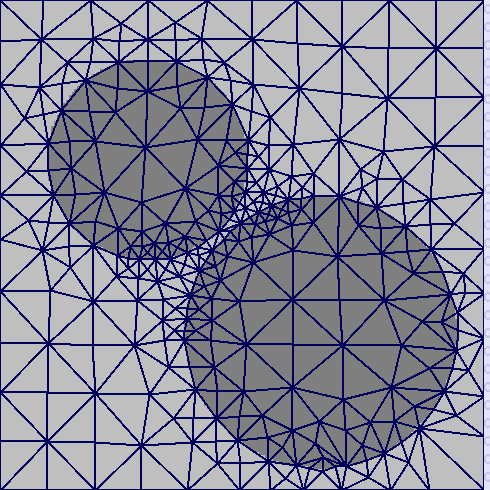
Remove the Restrictions: Execute /active_area/all to make the whole mesh active again. You should have something like Figure 2.3. . [18]
-
Play Around: See if you can improve the mesh. Use /adaptive_mesh/stack/undo to recover from mistakes.
[17] Change directories by using the D .. line to move up a directory, and the other D lines to move down, or by clicking on the directory name at the top of the window.
[18] You probably won't have exactly this mesh. Your random number generator probably doesn't generate the same numbers, and you probably didn't define the same active_area.


